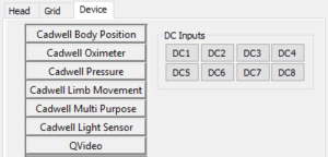
Connect the SenTec SDM to the Easy III Amplifier using any of the 8 DC inputs not already used. Note which number you are plugging which input into.

Open Easy III System Utilities
- Click System Setup, click Data Map, find the Data Map that you want to add/calibrate tcpCO2 on and click Edit.
- Check to see if there is already an item in the Data Map for tcpCO2. If there is, you can click the Edit DC Input Calibrations button and continue to Step 3.
- If there is no entry for tcpCO2 in the Data Map, click the drop-down arrow on the empty bottom line, scroll down and select tcpCO2:

- If there is no entry for tcpCO2 in the Data Map, click the drop-down arrow on the empty bottom line, scroll down and select tcpCO2:
- Click on the button labeled Edit DC Input Calibrations.
- In the window labeled DC Input Calibrations, either select the channel with the tcpCO2 data type from your list and click Calibrate or click the Add button, type tcpCO2 in the Name field if it isn’t already there and use the drop down under Data Type to pick tcpCO2.
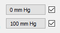
- Check that the device is set to 0 mm Hg and 100 mm Hg on the right side of the window.
If not, click on the button that is incorrect and change the Calibrated Value to the desired reading (here we had to change the default value from 50 mm Hg to 100 mm Hg).
- Click on the button labeled Read voltage from attached device for each calibration value. There can be a short pause while the software connects to the amplifier after you click this button, this is normal.
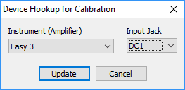
- Click on the button to the right that is labeled with Device Input.
- Change the input jack in the drop down to the DC Input that you have tcpCO2 connected to on the Easy III Amplifier (typically the end of the cable from the back of the SenTec device will be labelled as CO2). You need to choose a DC Input not being used by anything else in your Data Map.


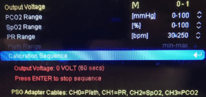
On the SenTec Device:
- If not already on, turn on the SenTec using the switch on the back of the device.
- Press the menu button, it is the top left button of the six located on the right side of the screen.
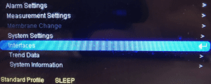
- The menu will display on screen.
- Use the up/down arrow keys to highlight Interfaces.
- Highlight it and press the Enter button (middle button on the right side of the screen).
- Choose Analog Outputs and Enter.
- Calibration sequence and Enter.
- It will send 1 volt – wait 60 seconds and it should go to 0 volt but you can press the Enter button to change to 0 at any time.


In Easy III:
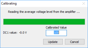
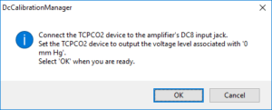
- Click on the button in your Device Calibrations that is labeled 100 mm Hg. A DcCalibrationManagerwindow will appear asking you to connect and if you are ready. Click OK.
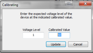
A Calibrating window will appear and a bar will move across. The Calibrated Value box should show 100. Click on the Update button when it appears.
- After 60 seconds, the SenTec will switch to sending 0 volts but you can press the Enter button to change to 0 at any time before then. Click Enter or wait for the device to switch to 0 Volts.
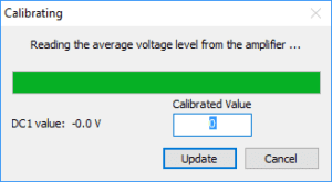
- Click on the button in your Device Calibrations that is labeled 0 mm Hg. A DcCalibrationManager window will appear. Click OK.
- A Calibrating window will appear and a bar will move across. The Calibrated Value box should show 0. Click on the Update button when it appears.
- On the SenTec SDM, press the Enter button again to end the calibration signal.
- In Easy III, click Update at the bottom of your Device Calibration window.
- At this point you can either follow the above steps to calibrate any of the three additional channels (SpO2, PR, Pleth) or you can Click OKto close the DC Input Calibrations
-
To Calibrate an additional signal:
- In Easy III, follow the instructions starting at 2a in this document to add additional Data Type channels for any of the signals you would like. There are already data types for SpO2, Pleth, HeartRate and they can be named uniquely to help identify them.
- When you have added the channels you are interested as Data Types, then you can calibrate them following the above instructions starting at step 4.
- After you have calibrated all of the signals, Click OKon the DC Input Calibrations window
You should now be in the Edit Data Map window.
Check to see if you have entries for any of the above signals you calibrated (in our example here we have: tcpCO2, tcSpO2, tcPleth, tcPulse).
Also, check to see that they are set to the DC inputs that you calibrated above.
- If they do not have associated Inputs, select the blank box in the Input column to the right of the Data Type, Click on the Device tab on the left side. Click on the DC Input that your signal is plugged into.
- A DC Input Calibrations box will appear. Choose tcpCO2 [or tcSpO2, tcPleth, tcPulse] from the list and click Select. It should fill with the settings for that channel. You can click the 0 to 100 button to alter the range that will display on the PSG trace.
- Repeat as needed.Click OK at the bottom of your Edit Data Map window. Click OK at the bottom of the Edit Data Maps window.After calibration and adding to your Data Map, you will need to add the channels to any montages you would like to see them in. From within the Edit Montage, you will now find your new entries on the Data Type tab.

Nov 28, 2016 246 Easy III EEG/PSG FAQs